Operations
KPU Facilities
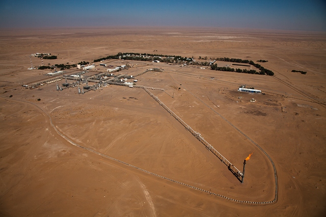
The KPU is located in the Kamil field which is about 25 km east of the CPU; The KPU facility handles more than 1,100 MMSCFD of gas in the production separators.
The KPU has two 420 MMSCFD cryogenic plants.
Most of the gas from the production separators is processed in the two cryogenic plants prior to YLNG gas delivery. Otherwise it will go to injection wells through the injection manifolds.
The KPU has two cryogenic plants the design of the two KPU cryogenic plants are identical to the CPU cryogenic plant. Each cryogenic plant has two NUOVO PIGNONE Frame 5 turbines powering 3 stages of recompression.
There are four generators (2750 kW each), 800 kW diesel generator, water wells, living quarters, sewage treatment plant and necessary facilities
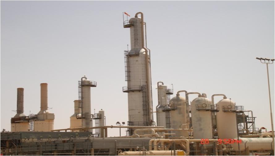
Plant Operations (Gas Processing)
Plant operations operate 4 NGL & 1 LOP extraction plants, residual reinjection gas compressors RGC, LPG storage systems, including LPG loading stations, pressure letdown stations (LDS) systems, residual transferring gas compressor for YLNG feed and utilities systems such, power generators, instrument air compressors and fire fighting systems. Additionally, they provide fuel gas to PEC pressure letdown station and pipe line operations, as well.
Gas processing plants were built at two oil and gas well gathering and separation centers, CPUI & KPU.
LOP and 4 CPU RGCs were built at the end of the eighties, CPUI & 2 RGC plants and KPU 2 NGL extraction plants with 4 RGC plants were built at the beginning of the nineties. The newly built in CPU-II gas processing unit with gas transfer compressor and LDS systems were built in 2009-2012,
Each gas processing plant was designed for processing a 420 mmscftd associated gas from HP separators, passing through a treatment section removing contaminations such entrained moisture, solid particles and liquid droplets, the ready gas for processing is cooling and finally directed to the last separation stage fractionation systems. Process outlet streams are LPG, C5+ and residual gas.
LPG product streams (20000- 25000 bbls/d), through two pipelines, directed to LPG storages and via a 3 x2 loading stations feeding the local market.
C5+ product streams (approx. 7000 bbls/d) either injecting with the produced oils or directed to the blending tank at refinery mixing with high octane imported gasoline, feeding the local market.
Residue gas streams through the RGC injected into CPU, KPU reservoirs, including Al-Raja reservoir, and YLNG feed through the LDS.
Al-Raja field oil and gas wells gathering and LTS separation system, interconnected with KPU facilities, the producing liquids and gas through a pipe line separated in KPU separation systems mixing the gas with KPU gas feeding KPU gas plants, residue from KPU RGC manifold, pipelined to Al-Raja compressor suction for final re-injection
LOP is an absorption gas processing unit, and considered the first commissioned gas processing unit, but currently not online, could be utilized in the future exploration plans.
CPU Lean Oil plant & RGC's
The lean oil C5+ plant (commissioned in 1988) is an ambient oil plant which can recover approximately 3,000 BPD of LPG and 6,000 BPD of C5+ from the inlet flow of 500 MMSCFD of rich natural gas, this plant also include a 10,000 BPD condensate stabilizer which was added in 1991.
The reinjection gas compressor (RGC’s) consist of two groups, the first group consist of four (16,000 BHP each) gas turbine driven centrifugal compressors with four stages of compression. The 1st stage of each RGC unit is designed to boost 20MMMSCFD of gas from 250 to 660 PSIG. The 2nd stage boost is from 660 to 1060 PSIG and is designed for 60 MMSCFD. The 3rd and the 4th stages boost from 1060 to 1975 to 3500 PSIG and are rated at 150 MMSCFD each. The second group consists of two gas turbine driven centrifugal compressors (25,560 BHP each) with three stages of compression, all three stages are rated of 200MMSCFD; and each compressor compresses the gas from 550 to 3300 PSIG.
There are three recovery compressors (VRC’s) each having 1,500 BHP electric motor which driven a two stage centrifugal compressor, they compress the gas from 2 to 250 PSIG. The capacity of each unit has a first stage capacity of 5.3 MMSCFD and a second stage capacity of 13 MMSCFD.
The facility provides all of its own electric power. There are three 13,000 KW (13 Mega watts) electric generators units driven by 16,000 BHP gas turbine.
Al-Raja Plant
Al Raja plant is located about 20 KMs east of KPU facilities
(Kamil Processing Unit). It was constructed in 1992 with one stage -an Avon
compressor driven by a Rolls Royce turbine receiving 400MMCFD residue gas from KPU
via a 16” pipeline with a pressure of 3000 psi which was compressed to 5500 psi
before being injected into the field via the injection manifold into injection wells
AR#1,2,4,9,1015,16&19, Asaeeda#1 and DAW#1.
Al-Raja
is accommodated with auxiliary utilities of two caterpillar gas power
generators one MW each, two Ingersoll-Rand air
compressors, a fuel gas heater, a utility water system, and accommodation.
Production
test separator and manifold receiving 400 MMSCFD (million standard cubic feet
per day) condensate from wells and send it to KPU via 20” pipeline to slug catcher
in KPU with the pressure of 1500 psi. Each production well is choked from
approximately 3500 psi to 1600 psi and goes through a gas heater to compensate for
temperature drop due to pressure drop before going to the production manifold.
Al Raja facility expanded in 1999 with: -
Two
stages NUOVO PIGNONE compressor driven by a NUOVO PIGNONE Frame 5 turbine, two low-temperature
separators associated with heat exchangers, two caterpillars gas-powered
generators one MW each, and new MCC.
Injection
& production manifolds expanded & five injection wells
AR#21,25,28,30&31 drilled & production wells as well.
Condensate
is divided into two ways in the production manifold;
1-
To low-pressure manifold with the pressure of
1400 psi & into a 20” pipeline direct to KPU slug
catcher with a quantity of approximately 400 MMSCFD
to be processed there.
2-
To high-pressure manifold with a pressure of 2200
psi & 400 MMSCFD to low-temperature separators (LTS) with 200 MMSCFD each.
Pressure & temperature dropped by JT v/v from
2200 psi & 120Fo to 1600 psi & 70 Fo, enter the separator &
separation process takes place inside LTS (T=70 Fo, 1600 psi).
The liquid
is drawn from Low-temperature separation) LTS (underneath
through a 6” pipeline to production 20” pipeline (20,000 BBD
in early days and depleted by years to around 1000 BBD in 2015) going to KPU
slug catcher.
Residue
gas is taken from TS’s top and goes to 1st stage scrubber, to the suction of the
LP compressor. The gas is compressed to 3000 psi, going to 1st stage gas/air
coolers (10 fans), to 2ed stage scrubber, and the suction of the HP compressor. The gas was compressed to 5500 psi and
sent to 2ed stage coolers to be cooled to 130-140 Fo before going to the injection
manifold.
In
sept-2010 the Avon compressor stopped due to a lack of gas during the g gas
diversion to the YLNG project.
Novo Pignone K-3451 compressor discharge to injection manifold
decreased to around 4900 psi due to Avon K-3351 compressor stop.
Novo
Pignone K-3451 compressor stopped on 17/4/2015 no more injections due to a lack
of gas from KPU due to diversion to YLNG.
In July
2015 a modification was carried out to the residue gas 16” pipeline coming from
KPU in which a 12” line connected from the 16” line
to the outlet line of LTS’s going to N.P K-3451 suction to enable CPUII
operating.
K-3451
N.P compressor recently has been running with gas feed either from CPUII or KPU
residue gas with a flow rate of 390 MMSCFD, 1350 psi suction pressure, and 4500
psi discharge pressure injecting to AR#1,2,10,16,19,28 &30 injection wells.
Most injection & production wells are closed due to ongoing circumstances.
Modifications to the LPG Storage and Loading Station
10-11-2022.jpg)
Modifications to
the LPG Storage and Loading Station
Introduction
SEPOC is the Republic of
Yemen's leading national Exploration and Production Operations Company. It is
the upstream Operator of Yemen's premier Block (18) in the city of Mareb and
the largest and second largest producer of gas and oil in the country
respectively.
LPG stands for “Liquefied
Petroleum Gas” and the term is used to describe two Natural Gas Liquids:
propane and butane, or a mix of the two. LPG is stored in a cylindrical tank. The
reason why LPG is stored in a spherical tank is liquid form gas is to be
highly pressurized to keep it in liquid form. LPG is used for many purposes
such as fuel for gas barbecue grills and gas cooktops and ovens, gas
fireplaces, and in portable heaters.
SEPOC LPG loading stations
are designed for the transfer of dangerous pressurized liquids from
stationary to mobile tanks.
Project Name
Modifications to the LPG
Storage and Loading Station
Project Main Objective
The purpose of the project is
to maintain the LPG storage system and keep its loading station running at
maximum production capacity. Moreover, this project comes to meet the set related
safety and security maintenance regulations.
Project Methodology
Connecting the company's two systems for storing and loading LPG
What is the two SEPOC LPG storing and loading
systems?
1- The
old system was established during the management of the former operator of
block 18 (Yemen Hunt Oil Company).t mainly consists of a 6” pipeline that
transferred the LPG product extracted from three cryogenic plants (CPU-I, KPU-A
& KPU-B) and pumped to 10 horizontal cylindrical vessels (bullets) with a
nominal capacity of each (92 m3), three loading pumps and two loading bays with
two loading point each, recently the pipeline of the LPG product extracted from
the new cryogenic plant CPU-II connected to the old LPG storage.
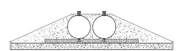
2- The
new system was established (with new cryogenic plant CPU-II) during the YLNG
project, mainly consisting of a 6” LPG pipeline from CPU-II to the storage
area, two pressurized embankment mounded bullets with a capacity of 520 m3 gross, two loading pumps, one loading bay with
two loading points, new fire water system, F&G system, and safety shutdown
system.
Why Modification?:
· For
more Operational flexibility,
· Storage
of LPG in Mounded Bullet provides an intrinsically passive & safe
environment and technologically proven safe device.
Tie-in project implementation:
· SEPOC’s
primary objective is the save storage and operation of the trucks’ loading
station.
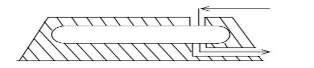
· Nowadays
the storage of dangerous gases becomes a challenging problem. The use of
mounded bullets is one of the feasible solutions to the problem. The design
aspects of mounded storage vessels are more complicated than conventional
above-ground spheres or bullets. Mounded bullets are horizontal pressure
vessels that are intended for the pressurized storage of liquefied petroleum
gas (LPG) under ambient temperature. In mounded storage facility, a mound of
earth or suitable inert material is provided to cover the bullet, which is kept
above ground, complete except for nozzles, and manhole covers. Mounded bullets
are considered to be a safer option for LPG storage than conventional methods,
such as Horton spheres, buried storage, etc. because situations leading to a
possible Boiling Liquid Expanding Vapour Explosion (BLEVE) are eliminated. The
mound protects the vessel from engulfment by fire, radiation from a fire nearby,
acts of sabotage terrorism, and vandalism. Mounded storage is also used in
situations where minimization of visual impact is important. The mounds reduce
the visual impact of the storage site. As they have a sand cover around them,
they can take the impact of external projectiles or flying objects. The dished
ends of the bullets are the weakest points of material construction susceptible
to catastrophic failures. Hence, they are to be directed away from the process
or occupied areas.
· Based
on these factors, the management decision was to implement the tie-in project
between the two systems using the existing tie-in streams under the new system
battery limit.
Execution Plan:
· Inspect
and replace all corroded lines of the old system inside the area,
· Installation
of insulation gasket at the battery limit of the old system pipelines coming
from the plants,
· Tie-in
LPG from the KPU-A & KPU-B cryogenic plants to the new system,
· Tie
in LPG from the CPU-I cryogenic plant to the new system,
· Tie
in the new and existing vapor lines,
· Tie-in
for interconnecting the new and existing loading pumps suction headers,
· Tie-in
for interconnecting the new loading pumps discharge header with existing
discharge lines going to the loading bays #1 & #2.